Pages

Tuesday, October 2, 2018

CONTEXT SENSITIVE HALF TIME [CSHT]

Screen Shot 2018-09-21 at 11.24.29 AM
  • Context sensitive half-time is deined as the time for the plasma concentration to fall to half of the value at the time of stopping an infusion
  • The half time will usually alter in the setting of varying durations  of drug infusion
  • The higher the ratio of distribution clearance to clearance due to elimination, the greater the range for context-sensitive half-time
  • The longest possible context-sensitive half-time is seen when the infusion has reached steady state, when there is no transfer between compartments and input rate is the same as elimination rate
  •  Draw and label the axes; draw the curve for the drug with the shortest CSHT first before plotting the others
  • REMIFENTANIL: Here the elimination always dominates distribution and so there is very little variation in CSHT with time and so it is context insensitive. Draw a straight line starting from the origin and becoming near horizontal after the CSHT reaches 5 min. This demonstrates that the half time is not dependent on the length of infusion as clearance by plasma esterases is so rapid. For remifentanil the
    longest possible CSHT is only 8 minutes
  • PROPOFOL: For propofol the clearance due to elimination is similar to that for distributioninto the second compartment, so plasma concentration falls rapidly after a propofol infusion mainly due to rapid eliminationwith a smaller contribution from distribution. Propofol is not context insensitive as its CSHT continues to rise; however it remains short even after prolonged infusions. Starting at the origin, draw a smooth curve rising steadily towards a CSHT of around 40 min after 8 h of infusion.
  • ALFENTANIL: The curve rises from the origin until reaching a CSHT of 50 min
    at around 2 h of infusion. Thereafter the curve becomes horizontal. This shows that alfentanil is also context insensitivefor infusion durations of 2 h or longer
  • THIOPENTONE SODIUM: The curve begins at the origin but rises more steeply than the others so that the CSHT is 50 min after only 30 min infusion duration. The
    curve should be drawn like a slightly slurred build-up exponential reaching a CSHT of 150 min after 8 h of infusion. As the CSHT continues to rise, thiopental does not become context insensitive
  • FENTANYLThe most complex curve begins at the origin and is sigmoid in shape. It should cross the alfentanil line at 2 h duration and rise to a CSHT of 250 min after 6 h of infusion. Again, as the CSHT continues to rise, fentanyl does not become context insensitive.
  • The maximum possible CSHT for propofol is about 20 minutes, compared with 300 minutes for fentanyl
  • It is important to realize that the CSHT does not predict the time to patient awakening but simply the time until the plasma concentration of a drug has fallen by half. The patient may need the plasma concentration to fall by 75% in order to awaken, and the time taken for this or any other percentage fall to occur is known as a decrement time.
  • Decrement time: The time taken for the plasma concentration of a drug to fall to the specified percentage of its former value after the cessation of an infusion designed to maintain a steady plasma concentration (time). The CSHT is, therefore, a form of decrement time when the specified percentage’ is 50%.
  • Although the CSHT for propofol has a maximum value of about 20 minutes, during long, stimulating surgery infusion rates will have been high and the plasma concentration when wake-up is required may be very much less than half the plasma concentration at the end of the infusion. Thus time to awakening using propofol alone may be much longer than the CSHT. This is why the TCI pumps display a decrement time rather than a CSHT.
  • When using propofol infusions, the decrement time is commonly quoted as the time taken to reach a plasma level of 1.2 μg.ml1, as this is the level at which wake up is thought likely to occur in the absence of any other sedative agents.
  • It must be remembered that after one CSHT, the next period of time required for plasma concentration to halve again is likely to be much longer. This relects the increasing importance of the slower redistribution and metabolism phases that predominate after re-distribution has taken place. This explains the emphasis on half-time rather than halflife: half-lives are constant whereas half-times are not!

MEDIASTENAL TUMOURS & THE ANESTHESIOLOGIST: SPECIFIC POINTS

  • A preoperative CT scan will show the site, severity, and extent of the airway compromise to assess the level and degree of obstruction.
  • Assess the vocal cord function preoperatively
  • Lung function tests to look for the extent of intrathoracic or extrathoracic obstruction.
  • ECHO to rule out pericardial effusion and cardiac compression.
  • Premedication with benzodiazepine is generally avoided if there is risk of airway compromise.
  • Airway equipment—rigid bronchoscopy and difficult airway trolley, jet ventilation, cardiopulmonary bypass (CPB) should be there as standby. Femoro femoral bypass is the most common setup.
  •  
  • COMPLICATIONS DUE TO MASS EFFECT OF THE TUMOUR: 
  •  
  • Vascular compromise—SVC Obstruction ( SVCO ) and pulmonary vessel obstruction
  • Laryngeal nerve palsy
  • Dysphagia
  • STRIDOR and airway compromise may be an important symptom
  • Inspiratory stridor (laryngeal)—obstruction above the level of glottis
  • Expiratory stridor (tracheobronchial)—obstruction in the intrathoracic airways
  • Biphasic stridor—obstruction between glottis and subglottis or a critical obstruction at any level
  • Sometimes you may have to go for a microlaryngoscopy tube (MLT)
  •  
  • TAKE CARE:
  • Aim to avoid worsening of cardiac compression, airway occlusion, and SVC obstruction.
  • IV cannula in the lower extremity
  • Induction in sitting position (semi Fowler’s position)
  • Inhalational (preferred choice) or IV induction agent titrated to effect
  • Choose spontaneous ventilation with LMA
  • Awake fibreoptic technique if intubation is necessary with a reinforced smaller calibre and longer endotracheal tube
  • Postoperative airway obstruction due to airway oedema, tracheomalacia, and bleeding warrant the need for awake extubation in ITU. The following steps would aid in an uneventful extubation:
  • Test for leak around the endotracheal tube cuff.
  • Administer dexamethasone or chemo radiotherapy in sensitive tumours to shrink size of tumour.
  • Use adrenaline nebulisers.
  • Extubate over airway exchange catheters.
  •  
  • SVCO: challenges during anaesthesia
  • Need for supplemental oxygen
  • Orthopnoea—induction in the sitting-up position
  • IV cannula in the lower extremity
  • Airway oedema
  • Mucosal bleeding
  • Laryngeal nerve palsy
  • Haemodynamic instability due to decreased venous return
  •  
  • OTHER CONCERNS 
  • General anaesthesia, causes loss of intrinsic muscle tone, decreased lung volumes, and decreased transpleural pressure gradient
  • Positive pressure ventilation, can precipitate severe hypotension and also increases intrathoracic tracheal compression
  • Coughing, as it can cause complete airway obstruction by positive pleural pressure, increasing intrathoracic tracheal compression
  • Following gas induction, the patient stops breathing and if you are unable to ventilate her: Follow difficult or failed intubation guidelines. But cricoid puncture and emergency tracheostomy are futile if the level of airway obstruction is at the intrathoracic tracheobronchial tree: Try a change in position—lateral, sitting up, or prone—to decrease the mechanical effect of the tumour. Avoid positive pressure ventilation for fear of luminal closure. Low-frequency jet ventilation with Sander’s injector or high-frequency translaryngeal jet ventilation with Hunsaker’s catheter is one option. CPB bypass and ECMO to restore oxygenation when other measures fail.
  • Following chemotherapy in ICU, if patient develops hyperkalemia, Tumour Lysis Syndrome should be there in the differential diagnosis
  • ALSO NOTE
  • During inspiration, the intrathoracic airways expand along with the expanding lungs. In contrast, the extrathoracic airways diminish in caliber during inspiration due to their intraluminal pressure being lower than the atmospheric pressure. The reverse happens during expiration.
  • Flow volume loop inupper-airway obstruction:
  • Fixed lesions[extrathoracic or intrathoracic] are characterized by lack of changes in caliber during inhalation or exhalation and produce a constant degree of airflow limitation during the entire respiratory cycle. Its presence results in similar flattening of both the inspiratory and expiratory portions of the flow-volume loop
  • Variable lesions are characterized by changes in airway lesion caliber during breathing. Depending on their location (intrathoracic or extrathoracic), they tend to behave differently during inhalation and exhalation.
  • In the case of an extrathoracic obstructing lesion, during inspiration, there is acceleration of airflow from the atmosphere toward the lungs, and the intraluminal pressure decreases with respect to the atmospheric pressure due to a Bernoulli effect, resulting in the limitation of inspiratory flow seen as a flattening in the inspiratory limb of the flow-volume loop. During expiration, the air is forced out of the lungs through a narrowed (but potentially expandable) extrathoracic airway. Therefore, the maximal expiratory flow-volume curve is usually normal.
  • Variable intrathoracic constrictionsexpand during inspiration, causing an increase in airway lumen and resulting in a normal-appearing inspiratory limb of the flow-volume loop. During expiration, compression by increasing pleural pressures leads to a decrease in the size of the airway lumen at the site of intrathoracic obstruction, producing a flattening of the expiratory limb of the flow-volume loop
  • Screen Shot 2018-09-19 at 1.34.27 AM

ETOMIDATE: THE BAD 'WOW' FACTORS

  • While it continues to be used infrequently in the UK it has been withdrawn in North America and Australia
  • The most notable and potentially serious side effect of etomidate administration is the suppression of adrenocortical steroid synthesis.
  • It suppresses adrenocortical function by inhibition of the enzymes 11-hydroxylase and 17-hydroxylase, resulting in inhibition of cortisol and aldosterone synthesis.
  • After a single bolus dose of etomidate, this adrenocortical suppression lasts approximately 6 h in healthy individuals. However in the critically ill, such suppression can last for days. In other words the situation in which it has the best cardiovascular proile is the unwell patient in whom the consequences of steroid inhibition are likely to be the most detrimental.
  • Etomidate is approximately 100-fold more potent a suppressor of adrenocortical function than it is a sedative-hypnotic. Consequently, an anesthetic
    induction dose of etomidate represents a massive overdose with respect to its ability to suppress adrenocortical function. And etomidates terminal elimination half-life is rather long. Thus, after just a single anesthetic induction dose of etomidate, many hours must pass before etomidates concentration in the blood falls below that which suppresses adrenocortical steroid synthesis.
  • It is within this mechanistic context that the strategy emerged to design analogues of etomidate
  • ANALOGUES:
  • MOC-etomidate[ relatively low potency and very rapid metabolism (1.) required the administration of extremely large doses]
  • CPMM etomidate[ it has an onset and offset of hypnotic action that are fast (1.) ]
  • Carbo etomidate[ less adrenocortical inhibition (2.)]
  • MOC-carboetomidate[ combines properties (1) and (2); but it's potency
    is very low which means that extremely large doses would need to be administered to maintain anesthesia ]
  • Involuntary movements (myoclonus) are commonly observed after etomidate administration, with some studies reporting an incidence as high as 80 % in unpremedicated patients
  • It has been suggested that it occurs because etomidate depresses inhibitory neural circuits in the central nervous system sooner and at lower concentrations than excitatory circuits.
  • Regardless of the mechanism, myoclonus can be significantly reduced or completely prevented by administering a variety of drugs with central nervous system depressant effects including opiates, benzodiazepines, dexmedetomidine, thiopental, lidocaine, and magnesium.
  • Pain at the injection site is another common side effect and its incidence is highly dependent upon the size of the vein into which it is injected and the formulation that is used.
  • Lipid emulsion and cyclodextrin formulations may reduce TRP channel activation, leading to less pain on injection
  • Postoperative nausea and vomiting is common with reported incidences as high as 40 %. It has been suggested that the emetogenic trigger in etomidate is the propylene glycol solvent and not the anesthetic itself.
  •  

Sunday, September 16, 2018

IDEAL POSITION OF TIP OF RIGHT IJV CATHETER

  • Different methods have been suggested in the literature
  • Catheter tips positioned approximately 3 cm below the right tracheobronchial angle will lie in close proximity to the atriocaval junction but will remain extracardiac in location
  • Pere P.W. studied correlation between the length of catheter inserted and patient's height and observed that catheters inserted through right IJV from midcervical point or lower puncture to Height/10cm ended in SVC, while those inserted more than Height/10 + 1cm, 47% ended in right atrium
  • Some studies argued that the catheter tip should lie above the pericardial reflection to prevent serious and potentially lethal complications like cardiac tamponade, malignant arrhythmias, placement in coronary sinus and tricuspid valve damage. The upper limit of the pericardial reflection cannot be seen on a plain chest X-ray, but it is generally accepted to be below the carina.
  • Most clinicians aim to place the catheter tip at the level of the carina with whichever formula they follow. This position carries the risk of migration, thrombosis, and malfunction.
  • A recent paper has demonstrated that a catheter with its tip positioned peripheral to the atriocaval junction was more likely to undergo internal repositioning and venous thrombosis.
  • The lower placement is preferred for left-sided IJV cannulations, because aiming the catheter tip placement above the pericardial reflection in this scenario is more likely to lead to oblique placement and abutment against the wall, which is a risk factor for perforation. It seems, therefore, that a free-floating catheter tip in a wider portion of the IJV is more important than placing the catheter above the pericardial reflection.
  • This becomes even more relevant in the light of the observations by Schuster and colleagues13that the pericardium can ascend alongside the medial wall of the SVC by up to 5 cm (mean 3 cm). Thus, catheter tip placement even 3 cm above the SVC–RA junction might not obviate the risk of tamponade in all patients.
  • Recently many studies have questioned the placement of the catheter tip in the middle SVC. They argue , emphasizing the importance of having a free-floating tip (not abutting the vessel wall) rather than its placement above the pericardial reflection. This can be achieved by placing the catheter tip in lower SVC and upper RA (target zone, within 2 cm above and 1 cm below the SVC–RA junction). In this position, the SVC is wider, meaning that the catheter tip is likely to float freely with minimal chance of abutment. Furthermore, a catheter placed in this position is amenable to confirmation by TOE.
  • Ahn and colleagues have suggested a radiological landmark-based technique for ‘parking’ the catheter within the target zone. They adjudged the depth of CVC insertion by summing [1] the distance between the sternoclavicular joint and the carina (measured offline from the chest radiograph using an internal measuring tool available on the picture archiving and communication system), [2] the distance between the point of insertion and the sternoclavicular joint, and [3] 1.5 cm. The eventual location of the CVC tip was confirmed by TOE. The authors concluded that the catheter tip was positioned more accurately and the determined depth of CVC insertion correlated better with the actual distance from the skin insertion point to the RA–SVC junction with the radiological landmark-based technique compared with Peres’ formula of central venous catheterization via the right IJV
  • N.B: Also note that from the right internal jugular and left subclavian approaches, the veins respectively take straight and gently curving trajectories to the superior vena cava. However, the right subclavian vein takes a near-right angle turn into the superior vena cava, and the left internal jugular approach incorporates two turns, one into the brachiocephalic vein and a second into the superior vena cava. These turns create potential for the venous side walls to be punctured by a dilator failing to negotiate a curve appropriately.

  • Ref: Quest to determine the ideal position of the central venous catheter tip D. K. Tempe1,* and S. Hasija, British Journal of Anaesthesia 118 (2): 148–50 (2017)


IMPEDENCE AND RESISTANCE

  • Impedance and resistance are terms used to describe the opposition to electrical current flow.
  • Resistance is used to describe opposition to flow in DC circuits, whereas impedance is used for AC circuits.
  • Unlike direct currents, alternating currents exhibit reactance (capacitive and inductive) because they have frequency and are phase associated.
  • In AC circuits, impedance (Z) consists of a real part (ohmic resistance) and an imaginary part (reactance of an inductor or capacitor). It is measured in ohms, and is the total opposition to current flow
  • Capacitors placed in DC circuitscreate an increasing resistance to current flow. This is because the charge at the negative plate of the capacitor accumulates, until maximum capacitance is reached and current flow ceases.
  • Capacitors in AC circuitsallow current to flow, as the alternating direction of current flow prohibits a significant build up of charge on one of the plates.
  • Reactanceis the resistance to AC that a capacitor or inductor exhibits and is inversely proportional to frequency.
  • This principle is used in filters to screen out DC currents and low frequency AC.
  • Inductors are coils of conducting wire wound around a ferrous or air core.
  • An increasing current flowing through an inductor generates a magnetic field around it. This magnetic field in turn creates an electromagnetic force, which opposes the current flow, known as back-emf.This effect is known as inductance, and its SI unit is the henry (H).
  • In a circuit where the rate of current change is 1 A/s, an inductance of one henry would generate one volt across the inductor.
  • Henry (H) = Voltage (V) × Time (s) / Amperes (A)
  • When the power is switched off, collapse of the magnetic field induces flow of electrons in the inductor and circuit, prolonging the flow of current for a short period.
  • Inductors placed in DC circuits will initially encounter transient resistance while the magnetic field is established. Once a steady state is reached, the reactance is negligible.
  • Conversely, inductors in AC circuits encounter increasing reactance proportional to the frequency. This is because the creation and subsequent reversal of magnetic field development produces a constant back-emf resisting current flow. Therefore, high-frequency AC will cause a high reactance in the inductor.
  • Inductors are used to filter out high-frequency alternating currents, or to smooth out the effect of power surges in monitoring equipment

LASERS IN MEDICINE

    LASER is an acronym for Light Amplification by Stimulated Emission of Radiation.
    A laser comprises a laser tube constructed from an active lasing medium that can be a gas, solid or a liquid, with a mirror at each end of the tube
    Lasers produce an intense parallel beam of coherent monochromatic light (one specific wavelength of light) by the stimulated emission of photons from excited atoms
    Injecting energy from an external source (pumping) causes the lasing medium to become excited. Gas lasers are excited using an electric current applied to either end of the laser tube, while solid state and liquid lasers are excited using a high intensity light source. The mirrors cause photons to bounce back and forth within the laser medium, triggering further emission of photons by the process of stimulated emission. One mirror is partially reflective which allows some photons to escape in the form of the laser beam. The beam is then focused as required
    Electrons of atoms within a lasing medium normally reside in a stable low-energy level known as the ground state. Pumping excites electrons, raising them to higher energy levels. Because higher energy states are unstable in comparison to the ground state, there is a tendency for electrons to release excess energy and return to lower energy levels. This process is known as decay.
    As an electron decays from the metastable to ground state, it emits a photon of energy. If this photon strikes an excited electron in the metastable state, it incites it to emit another photon, which will have the same wavelength, waveform and direction as the incident photon. They are said to be in phase and coherent.
    Red and near-infrared lasers have the deepest penetration.
    Carbon dioxide lasers emit infrared light and have limited penetration, but are precise and can be used for cutting and vaporising.
    Argon lasers predominantly produce blue–green light at 488 and 514 nm, and are commonly used in ophthalmology.
    Neodymium-doped yttrium aluminium garnet (Nd:YAG) lasers have the deepest penetration and can cut and coagulate. They are used to resect gastrointestinal and bronchial tumours, and gynaecological lesions.
    LASERs are classified 1–4, 1 being least dangerous.
    Most medical lasers are class 3B and class 4. They pose a high risk to staff and patients.
    Lasers can ignite flammable material such as endotracheal tubes and surgical drapes. They can also cause airway and body cavity fires in the presence of high concentrations of flammable gases.
    The risk of airway fires can be reduced by using the lowest inspired oxygen concentration possible that achieves suitable oxygen saturations. In addition, using laser-safe endotracheal tubes with the cuffs filled with saline and dye helps to further reduce the risk of fires. The water in the cuff acts as a heat sink to reduce the likelihood of perforating and igniting the cuff with the laser. The dye provides a visual indication in the event of cuff perforation.

The Wheatstone bridge

  • The Wheatstone bridge is an electrical circuit that uses an arrangement of four resistors to measure an unknown electrical resistance.
  • The typical Wheatstone bridge contains a power source, a galvanometer (G), two resistors of known resistance (R1, R2), a variable resistor (R4) and an unknown resistance, which is the one to be measured (R3). The connection across CD containing the galvanometer is known as the bridge.
  • This circuit is sensitive to changes in the ratio of resistances across pairs of resistors.
  • When the voltages at C and D are equal, the ratios of resistances equal each other (R1/R2 = R3/R4), no current will flow through the galvanometer and the bridge is balanced.
  • By altering the resistance of the variable resistor R4 until the ratio of resistance across the limb ADB equals that of ACB, the bridge can be balanced, and no current flows across CD. By knowing the resistance required at R4 to
    balance the bridge, R3 can be calculated by using the equation R1/R2 = R3/R4
  • A strain gauge is either a foil arrangement or a conductive metallic strip. In the arterial transducer, strain gauges are mounted on a diaphragm.
  • The arterial pulsation is transmitted via a continuous column of fluid to the diaphragm, which causes it to stretch. The attached strain gauge will also stretch and its resistance increases. Conversely, when the diaphragm relaxes the resistance in the strain gauge falls. R3 is the strain gauge attached to the diaphragm, and the variable resistor R4 has been adjusted to match the resistance of R3 in the resting position, so that the bridge is balanced. Movement of the diaphragm would alter the resistance of R3, which unbalances the bridge and results a potential difference across CD. The resulting potential difference is quite small, so it is common to use a differential amplifier in place of the galvanometer to increase the sensitivity of the circuit in detecting the signal.

METHODS TO MEASURE THE CONCENTRATION OF A GAS

  • The Rayleigh refractometer utilises the refractive index of a gas to calculate its concentration.
  • Thermal conductivity is used in katharometers. In these devices, the cooling of a wire causes a change in resistance proportional to gas concentration.
  • Solubility is employed in devices such as rubber strips when an increase in length accompanies gas absorption.
  • Light emission features in the Raman light scattering measurement device.
  • Both infrared and ultraviolet absorption are used in gas concentration measurement.

ECG EMG EEG ; THE BIOLOGICAL SIGNALS

  • The movement of ions across cell membranes during the depolarisation and repolarisation of myocytes and neurones generates electric potentials.
  • Silver metal electrodes covered with a layer of silver chloride gel within an adhesive sponge pad can be used to measure these potentials at the skin.
  • Ion movement near the electrode–skin interface induces movement of chloride ions within the gel layer. The ion concentration gradient promotes electron production at the electrode.
  • A lead wire and voltmeter attached to the electrode allows measurement of the potential relative to a reference point. The reference point is usually a second skin electrode.
  • Signals are then amplified, processed and displayed.
  • Skeletal and cardiac muscles have higher amplitudes than cerebral neurones.This is because the amplitude of biological potentials is proportional to the number of simultaneously depolarising cells.
  • The frequency of potentials is related to the fluctuating ion activity across cell membranes.
  • Skeletal myocytes which undergo tetany have high frequencies of
    up to 1 kHz.
  • Conversely, cardiac myocytes have lower frequencies due to their refractory periods 

HUMIDITY AND ANESTHESIA

  • Absolute humidity is the mass of water vapour present in a given volume of gas at
    defined temperature and pressure (expressed as g of H2O/m3 of gas).
  • Relative humidity is the mass of water vapour present in a given volume of gas,
    expressed as a percentage of the mass of water vapour required to saturate the same volume of gas at identical temperature and pressure.
  • The amount of water vapour required to saturate a known volume of gas increases with temperature, i.e. a gas saturated at 20°C contains less water than the same volume, saturated at 37°C
  • Relative humidity (RH), can be calculated from the ratio of the mass of water vapour present (mP), to the mass required for satruation (mS) as
    RH = mP/mS
  • If droplets are present, supersaturation has occurred and relative humidity exceeds 100%.
  • From the gas laws, mass of a gas in a mixture is proportional to the partial pressure it exerts, thus: RH = water vapour pressure/ saturated water vapour pressure
  • Instruments used to measure humidity are called hygrometers. Examples include:
    Regnault’s hygrometer
    Hair hygrometer
    Wet and dry bulb thermometers
    Humidity transducers

PRESSURE AND ITS MEASUREMENT BY MANOMETER

💎Pressure = Force/Area
💎SI unit is Pascal
💎1Pa = 1N/m-2
💎It is the simplest method of pressure measurement
💎lt does not need calibration
💎So it can be used to calibrate other devices
💎The pressure is balanced against a column of liquid of known density - usually water for low pressures and mercury for higher pressures
💎The pressure is equal to the depth multiplied by the liquid density multiplied by the acceleration due to gravity; hence the commonly used units cm of H2O and mm of Hg
💎Mercury is 13 times more dense than water
💎The vertical height gives the pressure value

NEBULIZERS

  • Aerosols are small particles of liquids or solids suspended in a carrying gas
  • Medical aerosols can be produced by a nebulizer
  • The therapeutic efficacy of the aerosol is dependent on the liquid or solid’s ability to remain in suspension and the depth reached by the aerosol on inhalation, and is dependent on its stability. These are both determined by the particle size.
  • For liquid medication to enter the alveolithe droplets must be smaller than the diameter of the terminal bronchioles and fall within the size range of 0.005 µm to 50 µm in diameter.
  • For droplet sizes below 5 µm, gravity exerts a negligible effect.
  • Particles or droplets in the range 5 to 10 µm tend to deposit in the upper airways,with material below 5 µm penetrating further into the lungs.
  • Below 3 µm, the droplets enter the alveoli and become therapeutically beneficial.
  • Droplets below 1 µm are ideal; but if significantly smaller than this, the particles will be exhaled without having a therapeutic effect.
  • The temperature for an aerosol generated by a nebulizer must not exceed 37°C and the process must not alter the structure of the medication being carried.
  • This is the essential difference between vaporizers that generate a vapour and nebulizers that produce liquid droplets.
  • Jet or gas driven nebulizer (atomizers)
  • A high flow of gas is driven over a capillary tube that is immersed into the fluid to be nebulized. The high pressure air driven through the small orifice, generates negative pressure as a result of the Venturi effect. These nebulizers are simple and low cost, but small variations in gas flow rate can result in inconsistent delivery of aerosol to the patient.
  • Ultrasound driven nebulizer
  • The ultrasound nebulizer incorporates a ceramic piezoelectric transducer that changes electrical energy into mechanical energy (pressure oscillations). The transducer sits at the bottom of the chamber and vibrates at a frequency of 1.5 MHz. The vibrations are transmitted through the water. The diaphragm is in contact with the solution to be nebulized and violently shakes the solution into particles. At low frequencies, larger particles are produced, but at higher frequencies, a fine mist is generated
  • Ultrasonic nebulizers tend to produce a more consistent particle size than jet nebulizers and, as a result, produce a much greater deposition into the lungs.
  • But long-term use of ultrasonic nebulization might inadvertently affect surface tension stability in the alveoli

ANTIPSEUDOMONAL AGENTS

A 70 year-old female is intubated 5 days after hospital admission for hypoxemic respiratory failure after a witnessed aspiration event. Prior to admission, the patient lived in a nursing home, and recently was treated for left leg cellulitis with a short course of intravenous antibiotics. Her medications include metoprolol, metformin, glyburide, atorvastatin, and baby aspirin. Three days after intubation, the patient is noted to have a temperature of 102.5 °F, a blood pressure of 70/50 mmHg, a white blood cell count of 20.0 × 10⁹/L, with purulent secretions suctioned from the endotracheal tube. You decide to initiate antibiotic therapy. Which of the following is the best antibiotic regimen to initiate at this time?
A. Ceftriaxone and ertapenem
B. Imipenem, levofloxacin and vancomycin
C. Meropenem, cefepime, and piperacillin-tazobactam
D. Cefepime and daptomycin
E. Ceftriaxone and azithromycin
Answer: Yes its B!
Healthcare associated infections are almost routine in today’s critical care units, and the increasing rates of multi-drug resistant (MDR) organisms is taking a toll on our clinical and economic systems. Ventilator associated pneumonia (VAP) is a subtype of healthcare associated infection, and is defined by the diagnosis of clinical pneumonia 48–72 h after intubation. Duration of mechanical ventilation, antibiotic use history, geography, co-morbidities, and the epidemiology of the ICU population all determine the etiology of a nosocomial pneumonia. Aerobic gram negative bacilli are the most common pathogens causing VAP. These include Klebsiella, Escherichia coli, Pseudomonas, Acinetobacter, Stenotrophomonas, Enterobacter, Citrobacter, Proteus, and Serratia species. Pseudomonas is the most prevalent pathogen recovered in VAP. With the emergence of MDR organisms, Methicillin resistant Staphylococcus aureus (MRSA) is also an important etiology of VAP, as well as anaerobes such as Bacteroides species. Community acquired pathogens, including Streptococcus and Haemophilus species are less likely to cause VAP. The antibiotic regimen that should be initiated depends on the suspicion that a patient harbors MDR pathogens. Usually, if a patient is hospitalized for more than 5 days, the possibility of MDR pathogens is high, particularly if a patient has been on intravenous antibiotic therapy recently. The first line treatment would include an antipseudomonal cephalosporin or an antipseudomonal carbapenem or an antipseudomonal penicillin with Beta lactamase inhibitor, plus an antipseudomonal fluoroquinolone or aminoglycoside, plus an anti-MRSA agent . Azithromycin should be considered for atypical coverage if Legionella is high on the differential and in severely ill patients. If an MDR pathogen is not suspected, a third-generation cephalosporin or respiratory fluoroquinolone or non-antipseudomonal carbapenem should be considered. Daptomycin is not appropriate to use for pulmonary infections, as it is inactivated by surfactant.
See the pictures for examples of these drug categories

Wednesday, August 29, 2018

HUMIDIFIERS

Heat and moisture exchange filter (HMEF)
  • HMEF is inexpensive, disposable, passive and efficient enough to provide adequate humidification of dry gases for up to 24 hours.
  • It creates a sealed unit, near the patient end of the breathing system, containing a hygroscopic material such as calcium chloride or silica gel.
  • As the warm and moist gas from the patient reaches the HMEF, the moisture from the gas condenses onto the hygroscopic surface, simultaneously heating the element via the latent heat of condensation
  • With the next inspiration of dry cold gas over the moist element this process is reversed, warming and humidifying the gas the patient receives.
  • This process is about 80% efficient
  • The addition of a 0.2 mm filter renders the interface impermeable to bacteria and viruses
  • The disadvantages are that because it is a passive device, the HMEF is not 100% efficient and the patient will therefore lose heat and moisture over time, although this is negligible. Also, it adds dead space ranging from 8 mL in a paediatric HMEF to 100 mL in an adult, while the additional resistance can be up to 2.0 cm H2O ( may not create issues if respiratory function is not compromised significantly).
  • The hygroscopic material and filter can act as a dam to secretions, greatly increasing the work of breathing. This is easily remedied by vigilance and replacement.
Water bath humidifiers
  • Active water baths can achieve 100% efficiency and can also be used to heat the patient
  • But they are bulky and complex and better suited for patients requiring longer-term ventilation or oxygen therapy.
  • Passive water baths simply consist of a chamber of water through which the inspired gas is bubbled to achieve full saturation.
  • The disadvantage is that the temperature of the water limits the maximum achievable humidity.
  • Cooling of the water bath happens secondary to the latent heat of vaporization as the water is vaporized. This is remedied by an active system incorporating a heating element and thermostat.
  • The system is designed to keep the water bath at a specific temperature (40–60°C). This increases the temperature of the gas mixture and therefore the achievable humidity. This system is capable of delivering fully saturated gas at 37°C at high flow rates which represents a significant advantage over the HMEF.
  • All water baths need to include a water trap in their design, because the cooling of the gas as it moves away from the hot bath to the patient will result in condensation which can accumulate and could result in wet drowning. This risk may be minimized by heating the tubing and preventing condensation forming.
  • Water baths at around 40°C minimize the risk of scalding the patient’s airways with overly heated gas, but run the risk of creating an ideal environment for microbial growth.
  • By heating the water to 60°C the risk of bacterial contamination is reduced but the gas temperature must now be very carefully monitored.
  • A thermistor on a feedback loop to the water bath’s thermostat can adjust the temperature of the water, and therefore inspired gas, to ensure that the patient does not suffer from airway scalding.
  • The ideal size of water droplets for humidification is 5–10 microns. Smaller droplets will descend to the alveoli and larger ones will condense in the trachea.
  • Scalding is a risk associated with water bath types when the temperature within exceeds 37C.
  • Nebulisers are more efficient than water bath types of humidifiers. The Bernoulli effect describes the drop in pressure occurring at a jet, where velocity is greatest, which is employed to draw up water from a reservoir. This effect is used in spinning disc and gas driven humidifiers among others.

Wednesday, July 11, 2018

Latent Heat and its applications in anesthesia practice


  • Heat capacity: The heat energy required to raise the temperature of a given object by one degree. (J.K−1 or J.°C−1)
  • Specific heat capacity: The heat energy required to raise the temperature of one kilogram of a substance by one degree. (J.kg−1.K−1 or J.kg−1.°C−1)
  • But not all heat energy results in a temperature change. 
  • Latent heat: This is the heat energy that is required for a material to undergo a change of phase. (J) The heat is not utilised for raising the temperature, but for changing the phase.
  • If heat is applied to matter, temperature increases until the melting or boiling point is reached. At these points the addition of further heat energy is used to change the state of matter from solid to liquid and from liquid to gas. This does not cause a change in temperature. The energy required at these points is referred to as latent heat of fusion andlatent heat of vaporisation, respectively.
  • Specific latent heat is the heat required to convert one kilogram of a substance from one phase to another at a given temperature.
  • As temperature increases, the amount of additional energy required to overcome the intermolecular forces of attraction falls until the critical temperatureof a substance is reached. At this point the specific latent heat is zero, as no further energy is required to complete the change in state of the substance.

  • Variable bypass vaporisers function by passing a small amount of fresh gas through the vaporising chamber, which is fully saturated with anaesthetic vapour. This removes vapour from the chamber. Further vaporisation from the anaesthetic liquid must occur to replace the vapour removed, which requires energy from the latent heat of vaporisation. This cools the remaining liquid, reducing the saturated vapour pressure and thus the concentration of anaesthetic vapour delivered, resulting in an unreliable device.
  • Temperature compensation features help to overcome this problem; a copper heat sink placed around the vaporising chamber is one such example. Copper has a high heat capacity and donates energy required for latent heat of vaporisation, maintaining a stable temperature and reliable delivery of anaesthetic agent.
  • Evaporation of sweat is another example. It requires the latent heat of vaporisation, which is provided by the skin’s surface, exerting a cooling effect upon the body.
  • Evaporation from open body cavities can be a cause of significant heat loss from patients while under anaesthesia.
  • These principles are also applicable to blood transfusion. Blood is stored at 5°C and has a specific heat capacity of 3.5 kJ·kg−1·K−1. If cold blood were transfused into a patient without pre-warming, the heat energy required to warm the blood to body temperature would need to be supplied by the patient, which would have a significant cooling effect.

APPLICATIONS
  • Variable bypass vaporisers function by passing a small amount of fresh gas through the vaporising chamber, which is fully saturated with anaesthetic vapour. This removes vapour from the chamber. Further vaporisation from the anaesthetic liquid must occur to replace the vapour removed, which requires energy from the latent heat of vaporisation. This cools the remaining liquid, reducing the saturated vapour pressure and thus the concentration of anaesthetic vapour delivered, resulting in an unreliable device.
  • Temperature compensation features help to overcome this problem; a copper heat sink placed around the vaporising chamber is one such example. Copper has a high heat capacity and donates energy required for latent heat of vaporisation, maintaining a stable temperature and reliable delivery of anaesthetic agent.
  • Evaporation of sweat is another example. It requires the latent heat of vaporisation, which is provided by the skin’s surface, exerting a cooling effect upon the body.
  • Evaporation from open body cavities can be a cause of significant heat loss from patients while under anaesthesia.
  • These principles are also applicable to blood transfusion. Blood is stored at 5°C and has a specific heat capacity of 3.5 kJ·kg−1·K−1. If cold blood were transfused into a patient without pre-warming, the heat energy required to warm the blood to body temperature would need to be supplied by the patient, which would have a significant cooling effect.

OHM'S LAW

  • The strength of an electric current varies directly with the electromotive force (voltage) and inversely with the resistance. So I = V/R or V = IR where V is voltage, I is current and R is resistance.
  • The equation can be used to calculate any of the above values when the other two are known. When R is calculated, it may represent resistance or impedance depending on the type of circuit being used (AC/DC)
  • Resistance: The opposition to flow of direct current. (ohms, Ω)
  • Reactance: The opposition to flow of alternating current. (ohms, Ω)
  • Impedance: The total of the resistive and reactive components of opposition to electrical flow. (ohms, Ω)
  • The reactance of an inductoris high and comes specifically from the back electromotive force that is generated within the coil. It is, therefore, difficult for AC to pass.
  • The reactance of a capacitoris relatively low but its resistance can be high; therefore, direct current (DC) does not pass easily.

THERMISTORS AND THEIR USE IN ANESTHESIA


🔻
#thermistor is a temperature-sensitive resistor whose resistance changes with temperature.
🔻Most temperature-sensitive resistors are constructed from a semiconductor material (carefully chosen metal oxides) and the resistance increases with a fall in temperature (they have a negative temperature coefficient)
🔻So they are known as negative thermal conductivity (NTC) thermistors.
🔻A Wheatstone bridge circuit is used to measure the resistance accurately.
🔻The main disadvantage of thermistors is the non-linear resistance versus temperature characteristic, although this can be compensated for using an appropriate calibration equation programmed into an electronic measurement system.
🔻Thermistors remain highly popular due to their cost, miniature size and convenience.
🔻Thermistor probes are commonly placed in the nasopharynx, oesophagus, rectum or bladder (integrated with a urinary catheter).
🔻They have excellent accuracy and their small mass means that there is a quick response to variations in temperature.
🔻True or False? 'A thermistor comprises a junction of dissimilar metals'
🔻Answer: False. Dissimilar junctional metals are thermocouples

TURBULENT FLOW AND CLINICAL APPLICATIONS

⚱️The flow pattern of a river running over rapids is very different to the steadily flowing river (laminar flow). Here, the water’s path of travel becomes far less predictable than for laminar flow. This is an example of turbulent flow. An intermediate example is water flowing near the bank of a steadily flowing river, which often tends to meander, turning round in gentle circles. This is an example of eddies, the forerunner to full-blown turbulence.
⚱️As flow is, by definition, unpredictable, there is no single equation that defines the rate of turbulent flow as there is with laminar flow.
⚱️But, in well controlled circumstances the point at which flow changes from laminar to turbulent flow can be estimated using the Reynolds number, Re, which is named after Osborne Reynolds (1842–1912) of Manchester University, an engineering professor.
⚱️The Reynolds number allows us to predict whether turbulent or laminar flow would occur in a given system. The Reynolds number is a dimensionless quantity, i.e. it has no units. It is defined as the ratio of inertial and viscous forces. 
⚱️A Reynolds number <2000, where viscous forces predominate, predicts flow to be laminar. Between 2000 and 4000, both laminar and turbulent flow are anticipated. Above 4000, flow is likely to be completely turbulent because inertial forces are dominant. Critical flow is the point above which turbulent flow commences, which occurs at a Reynolds number of around 2000.
⚱️Viscosity is the important property for laminar flow
⚱️Density is the important property for turbulent flow
⚱️Reynold’s number of 2000 delineates laminar from turbulent flow (Tim and Pinnock: Re < 1000 is associated with laminar flow, while Re > 2000 results in turbulent flow)
⚱️A high Reynolds number means that the inertial forces dominate, and any eddies in the flow will be easily created and persist for a long time, creating turbulence. In a given airway with a known gas and flow velocity, the likelihood of turbulent flow can be predicted from Re.
⚱️APPLICATIONS: Both laminar and turbulent flow exist within the respiratory tract, usually in mixed patterns. Turbulent flow will increase the effective resistance of an airway compared with laminar flow. Turbulent flow occurs at the laryngeal opening, the trachea and the large bronchi (generations 1–5) during most of the respiratory cycle. It is usually audible and almost invariably present when high resistance to gas flow is encountered
⚱️APPLICATIONS: The principal sites of resistance to gas flow in the respiratory system are the nose and the major bronchi rather than the small airways. Since the cross-sectional area of the airway increases exponentially as branching occurs, the velocity of the airflow decreases markedly with progression through the airway generations, and laminar flow becomes predominant below the fifth generation of airway

LAMINAR FLOW

# When watching a steadily flowing river, the flow of water may be seen to be fastest in the middle, while near the banks of the river the water flows more slowly. 
# This behaviour is also observed in fluid travelling slowly along a wide straight cylindrical tube, where the fastest velocity occurring in the centre of the tube and the slowest at the edge where there is friction between the wall of the tube and the fluid. This is known as laminar flow.
# Viewed from the side as it is passing through a tube, the leading edge of a column of fluid undergoing laminar flow appears parabolic. The fluid flowing in the centre of this column moves at twice the average speed of the fluid column as a whole. The fluid flowing near the edge of the tube approaches zero velocity.
#  #Hagen (in 1839) and #Poiseuille, a surgeon (in 1840) discovered the laws governing laminar flow through a tube. If a pressure P is applied across the ends of a tube of length, l, and radius, r. Then the flow rate, Q, produced is proportional to:
*The pressure gradient (P/l) *The fourth power of the tube radius *The reciprocal of fluid viscosity . This is often combined as: (see the figure for the equation)
where Q is flow, ΔP is pressure gradient, r is radius, η is fluid viscosity and l is length
# Also note: Viscosity is the important property for laminar flow, whereas density is the important property for turbulent flow. Reynold’s number of 2000 delineates laminar from turbulent flow

Friday, June 29, 2018

PACEMAKER, AICDs AND THE ANESTHESIOLOGIST

  • The need for cardiac pacing results from conduction disorders of the heart, which may or may not be associated with IHD.
  • Permanent Pacemakers (PPM) are classified using a five letter code( See below)Screen Shot 2018-06-29 at 10.08.11 AM
  • For example DDDR means atrial and ventricular sensing (I), atrial and ventricular pacing(II) with adaptive(III) rate(IV) response
  • Most modern units work in DDD mode, and provide atrial pacing in the presence of atrial bradycardia and ventricular pacing after an endogenous/paced atrial depolarization, if a spontaneous ventricular beat is absent
  • KEY PERIOPERATIVE QUESTIONS: 1. Indication for pacemaker and associated cardiac comorbidities 2. Type of pacemaker; also how does the rate modulation work in that pacemaker? Chest x-ray will help to find the pulse generator siting and lead placement (atrium/ventricle/both) and number 3. When it was last checked 4. Requirement of diathermy for the procedure 5.Whether anticipating any other factor/s interfering with pacemaker function? 6. Surgical site proximity to the pacemaker 7. What is your plan to avoid inappropriate pacemaker function (e.g. change from demand to fixed rate mode) in case of interference? Cardiology/ Pacemaker programmer support may be needed for the same
  • WHAT ECG CAN TELL: 1. If native rhythm predominates--> patient not PPM dependent 2. If all beats preceeded by a pacemaker spike--> pacemaker dependent 3. No evidence of pacemaker activity--> magnet might be applied over the pulse generator to switch to fixed rate pacing. If pacemaker is activated by a magnet to pace at a fixed rate, spike may fall in the refractory period and fail to stimulate the ventricle 4. If pacemaker spike is not followed by p or QRS waves --> PPM malfunction
  • The characteristics of a PPM can be changed externally by application of a magnet or using radiofrequency generators, usually for a change of demand to fixed rate. Application of a magnet over a non-programmable VVI pacemaker will convert it to VVO asynchronous mode. The modern reprogrammable units need a cautious approach to the use of magnets. In this case, there is a risk of reprogramming ( with inappropriate settings), but it will remain in the asynchronous fixed rate mode, until the magnet is removed, after which the 'inappropriate' reprogrammed mode may take over
  • ABOUT THE RATE RESPONSE FUNCTION: Such PPMs may sense electrical activity or vibration (e.g. shivering) and cause a tachycardia in response. Some measure respiratory rate by sensing thoracic impedence and adjust HR accordingly. Some sense blood temperature and so may cause a tachycardia when warming a hypothermic patient. With hypokalemia, there is a risk of loss of pacing capture and with hyperkalemia, there is risk of VT or VF.
  • INTRAOPERATIVE STEPS: 1. If possible, avoid surgical diathermy; but if unavoidable, bipolar is safer than unipolar diathermy. 2. Monopolar where necessary, should be used in short bursts with at as low energy levels as possible 3. Diathermy plate should be kept on the same side, as far away from the PPM as possible 4. Cables from diathermy equipment also should be kept away from the PPM 5. Confirm device functionality on completion of the surgery
  • Surgical diathermy can cause 1. Ventricular fibrillation 2. 'Reprogramming' of programmable PPMs 3. Inhibition of demand function 4. Unit failure 5. Asystole
  • AUTOMATIC IMPLANTABLE CARDIOVERTER DEFIBRILLATORS (AICDs) and THE ANESTHESIOLOGIST: They consist of a set of lead electrode systems for sensing-pacing-delivery of shocks for cardioversion/ defibrillation; modern units can also function as DDD pacemakers. All AICDs should be deactivated with a programming device before surgery to avoid inappropriate shock delivery during electrical interference; in modern AICDs, the anti-bradycardia function can be left activated (Consult the manufacturer for this). The effect of magnets are inconsistent across devices; but modern units are inhibited by magnets. If required, external pads can be placed over the patient with external defibrillators ready to attach, for use in case any tachyarrhythmias occur during this period. Take all precautions as in the case of PPM. Postoperatively, the ICD should be checked and reactivated.

Thursday, June 28, 2018

DIATHERMY AND THE ANESTHESIOLOGIST

  • WHY WE SHOULD KNOW? 1.Anesthesiologist may be blamed if burns occurs due to malposition of the plate 2. It can interfere with monitors e.g. ECG and pulseoximeters 3. It can disrupt pacemaker function in a patient, having it.
  • Diathermy depends on the heat generated when a current pass through a tissue and is used to coagulate blood vessels and cut through tissues
  • A high frequency current is necessary for this, as myocardium is sensitive to DC and low frequency AC [the usual Mains frequency of 50 Hz will precipitate VF]. Very high frequencies have minimal tissue penetration and pass without harming the myocardium
  • A 0.5 MHz alternating sinewave is used for cutting and a 1.0-1.5 MHz pulsed sinewave pattern is used for coagulation
  • UNIPOLAR DIATHERMY & PROBLEMS: Here the forceps represent one electrode (small area, high current density and significant heat generation) and the diathermy plate ( indifferent electrode) over the patient represent the other electrode (large area, less heat). If the the plate is malpositioned, the current may pass through any point of metal contact* like ECG electrodes, metal poles of lithotomy, operation table etc, and may result in passage of high current density as the area of contact is small, resulting in a burn. So we should ensure that the plate is in close and proper contact with a large, highly perfused (will dissipate heat) area of skin (adhesive gels are useful). If we place it near to metal prosthesis (e.g. Hip), which has a low resistance than tissue, it will generate a high current density, resulting in burns. A unipolar diathermy can generate 150-400 Watts of energy.
  • BIPOLAR DIATHERMY: Current passes between the two blades of the forceps; so requires no plate; safer in patients with pacemaker. But can generate only 40 Watts of energy. So efficacy is less and may be used for coagulation of small blood vessels
  • OTHER PROBLEMS: Sometimes diathermies may cause ignition of skin preparation spirit. Newer diathermies dont have earthing; but if your machine is having earthing, an inappropriate earthing will result in current passing through other routes mentioned above*, resulting in burns.
  • Cautious use of diathermy is required in patients with pacemakers:Screen Shot 2018-06-28 at 12.54.13 PM

Tuesday, June 26, 2018

VOCAL CORD PALSIES; a complete description

Under normal circumstances, the vocal cords meet in the midline during phonation. On inspiration, they move away from each other. They return toward the midline on expiration, leaving a small opening between them. When laryngeal spasm occurs, both true and false vocal cords lie tightly in the midline opposite each other.
The recurrent laryngeal nerve (RLN) carries both abductor and adductor fibers to the vocal cords.
Selmon’s law: The abductor fibers are more vulnerable, and moderate trauma causes a pure abductor paralysis. Severe trauma causes both abductor and adductor fibers to be affected. N.B.:- Pure adductor paralysis does not occur as a clinical entity.
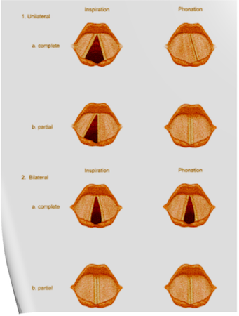
Scenario 1- PURE UNILATERAL ABDUCTOR PALSY: As adduction is still possible on the affected side, the opposite cord come and meet in the midline on phonation. However, only the normal cord abducts during inspiration.
Scenario 2- COMPLETE UNILATERAL PALSY OF THE RLN: Both abductors and adductors are affected. On phonation, the unaffected cord crosses the midline to meet its paralyzed counterpart, appearing to lie in front of the affected cord. On inspiration, the unaffected cord moves to full abduction.
Scenario 3- BILATERAL INCOMPLETE ABDUCTOR PALSY: When there is incomplete bilateral damage to the recurrent laryngeal nerve, the adductor fibers draw the cords toward each other, and the glottic opening is reduced to a slit, resulting in severe respiratory distress.
Scenario 4- COMPLETE BILATERAL PALSY OF THE RLN: With a complete palsy, each vocal cord lies midway between abduction and adduction, and a reasonable glottic opening exists.
Thus, bilateral incomplete palsy is more dangerous than the complete variety.
Scenario 5- DAMAGE TO SUPERIOR LARYNGEAL NERVE/S: Damage to the external branch of the superior laryngeal nerve or to the superior laryngeal nerve trunk causes paralysis of the cricothyroid muscle (the tuning fork of the larynx), resulting in hoarseness that improves with time because of increased compensatory action of the opposite muscle. The glottic chink appears oblique during phonation. The aryepiglottic fold on the affected side appears shortened, and the one on the normal side is lengthened. The cords may appear wavy. The symptoms include frequent throat clearing and difficulty in raising the vocal pitch.
Scenario 6- TOTAL BILATERAL PARALYSIS OF VAGUS NERVES: This affects the recurrent laryngeal nerves and the superior laryngeal nerves. In this condition, the cords assume the abducted, cadaveric position. The vocal cords are relaxed and appear wavy. A similar picture may be seen after the use of muscle relaxants.
N.B:- Topical anesthesia of the larynx may affect the fibers of the external branch of the superior laryngeal nerve and paralyze the cricothyroid muscle, signified by a “gruff” voice. Similarly, a superior laryngeal nerve block may affect the cricothyroid muscle in the same manner as surgical trauma does.
Reference: Benumof and Hagberg’s Airway Management, Third edition

Monday, June 25, 2018

NITROUS OXIDE ISOTHERM

An isotherm is a line of constant temperature
Compressed gases in a cylinder can either stay as a gas, or change state to form a liquid due to the higher pressure (both carbon dioxide and nitrous oxide do this).
A graph of pressure against time for nitrous oxide is shown below. The isothermal lines are shown for 40°C, 36.6°C and 20°C.
At 40°C, nitrous oxide is above its critical temperature and so it is a gas no matter whatever pressure is being applied.
When it is compressed (moving from right to left along the isotherm) the pressure increases smoothly. At 36.6°C (the critical temperature), as soon as the pressure reaches the critical pressure (72 bar), the gas becomes a liquid.
 At 20°C, once the pressure reaches 52 bar (the saturated vapour pressure of nitrous oxide at 20°C), some of the gas condenses so that liquid and vapour are both present. Further decreases in volume cause more vapour to condense, with no associated rise in pressure. When all the vapour has condensed to a liquid, any further reduction in volume causes a rapid rise in pressure.
In most circumstances, nitrous oxide is stored below its critical temperature of 36.4 C. It therefore exists in the cylinder as a vapour in equilibrium with the liquid below it.
To determine how much nitrous oxide remains in a given cylinder, it must be weighed, and the weight of the empty cylinder, known as the tare weight, subtracted. Using Avogadro’ s law, the number of moles of nitrous oxide may now be calculated. V/n= K, where V = volume of gas, n = amount of substance of the gas, K = a proportionality constant
Using the universal gas equation, the remaining volume can be calculated. PV = nRT, where P = pressure, V = volume, n = the number of moles of the gas, R = the universal gas constant (8.31 J/K/mol), T = temperature

CRITICAL TEMPERATURE AND PRESSURE

Critical temperature: The temperature above which a gas cannot be liquefied regardless of the amount of pressure applied. (K/°C).

At this point the specific latent heat is zero, as no further energy is required to complete the change in state of the substance.

Critical pressure: The minimum pressure required to cause liquefaction of a gas at its critical temperature. (kPa/Bar)

The latent heat of vaporisation is the heat energy required to change the state of a substance from liquid to vapour.

Wednesday, June 20, 2018

GAS LAWS AND THEIR IMPORTANCE IN ANESTHESIA


➡️
Boyle’s law
🔻At a constant temperature, the volume of a fixed amount of a perfect gas varies inversely with its pressure.
🔻PV = K or V ∝ 1/P . Also P 1 V 1 = P 2 V 2
Ⓜ️NEMO> water Boyle’s at a constant temperature
🔻P 1 V 1 relates to the pressure and volume in the cylinder and P 2 V 2 relates to the pressure and volume at atmospheric pressure. 
🔻For example, oxygen is stored at 13800 kPa (absolute pressure) in gas cylinders. If the internal volume of the cylinder is 10 litres, the volume this cylinder will provide at atmospheric pressure: 13800 × 10 = 100 × V2. So V2 = 1380 litres. However, 10 litres will remain within the cylinder, so 1370 litres will be usable at atmospheric pressure.
➡️Charles’ law
🔻At a constant pressure, the volume of a fixed amount of a perfect gas varies in proportion to its absolute temperature.
🔻V/T = K or V ∝ T
Ⓜ️NEMO> Prince Charles is under constant pressure to be king
➡️Gay–Lussac’s law (The third gas law)
🔻At a constant volume, the pressure of a fixed amount of a perfect gas varies in proportion to its absolute temperature.
🔻P/T = K or P∝T 
🔻Perfect gas: A gas that completely obeys all three gas laws or A gas that contains molecules of infinitely small size, which, therefore, occupy no volume themselves, and which have no force of attraction between them.
🔻It is important to realize that this is a theoretical concept and no such gas actually exists. Hydrogen comes the closest to being a perfect gas as it has the lowest molecular weight. In practice, most commonly used anaesthetic gases obey the gas laws reasonably well.
Other gas laws of relevance:
➡️Avogadro’s hypothesis: at a constant temperature and pressure, all gases of the same volume contain an equal number of molecules.
➡️Dalton’s law: the pressure exerted by a mixture of gases is the sum of the partial pressures of its constituents.
➡️Henry’s law: at a constant temperature, the amount of gas dissolved in a given volume of liquid is directly proportional to the partial pressure of that gas in equilibrium with the liquid.
🔻Henry’s law can be used to show that the amount of oxygen dissolved in blood is proportional to the partial pressure of oxygen in the alveolus. The amount of dissolved oxygen carried in blood is 0.023 ml dl−1 kPa−1 . At atmospheric pressure, this accounts for a very small and insignificant fraction of oxygen delivery. However, under hyperbaric conditions, the dissolved fraction increases and becomes a more significant source of oxygen delivery to tissues